Dual IMX219 MIPI Pipeline 1080p at 48 FPS on the TE0950 | Vitis 2024.2
I tried mixing them in the PL first. These camera boards do not bring out a frame-sync pin, so the two sensors never stay locked, and the CSI block also stalled if the next IP was not ready yet. Scaling each camera on its own and stitching in software was the way that actually ran. The cameras are at about 48 fps. I only send UDP at 25 fps, because this link falls back to 100 Mbit and a faster burst shows up as black lines.
Overview
This project is on the 2024.2 toolchain (Vivado + Vitis), bare-metal, no PetaLinux. lwIP (lightweight IP) is the small network stack Vitis gives you when there is no Linux. That is what sends the UDP packets. The board is a TE0950-03 (xcve2302-sfva784-1LP-e-S, board part trenz.biz:te0950_23_1lse:part0:1.1). UART is FTDI on J2 at 115200 8N1, not the Vitis console.
| Stream | Hardware | Control |
|---|---|---|
| cam0 | Onboard J15 Cam v2 / IMX219 | AXI IIC + AXI GPIO on the Versal |
| cam1 | CR00240 CSI on CRUVI HS1 (J10) | PS I2C0 through the Artix I2C mux |
The data path looks like this:
IMX219 1080p @ J15  ── CSI ── demosaic ── RGB8 ── VPSS 320×180 ── frame writer ──┐
                                                                                  ├─ DDR
IMX219 1080p @ HS1  ── CSI ── demosaic ── RGB8 ── VPSS 320×180 ── frame writer ──┘
                                                                                  │
                                                                    A72 stitch 640×180
                                                                                  │
                                                                    UDP → 192.168.8.220:55000
Each scaler writes a 320×180 tile. The A72 copies the two tiles next to each other and sends one 640×180 frame.
One important note up front: install the Trenz board files first (Tools → Settings → Board Repository) so te0950_23_1lse shows up under the Boards tab. MIPI CSI-2 Rx, v_demosaic, and VPSS need to be licensed. Program the Artix bitstream before expecting the HS1 camera’s I2C mux to ACK.
Block Design
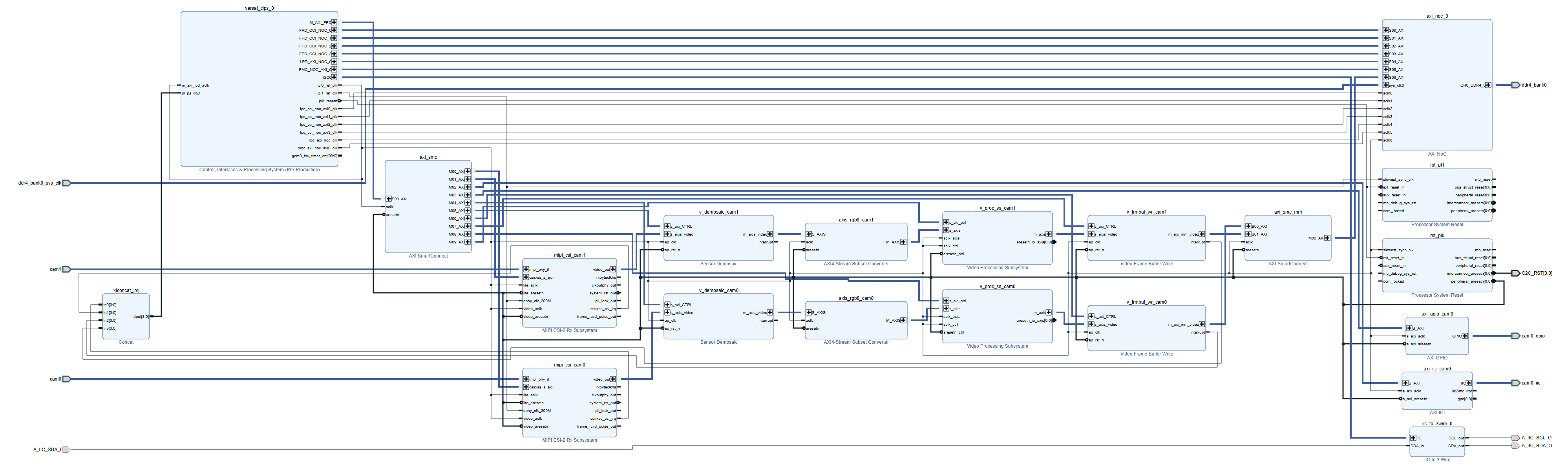
cam0 (J15) is the lower row. cam1 (HS1) is the upper row. Same pipe twice.
Block Design Breakdown
- versal_cips — the processor, a 100 MHz clock for video, a 200 MHz clock for the MIPI PHY, and the register bus.
- axi_smc — that register bus, split out to the CSI cores, J15 I2C, camera GPIO, demosaic, frame writers, and VPSS.
- The video pipe, twice. CSI → demosaic → 8-bit RGB → VPSS scale → frame writer.
- axi_smc_mm — both frame writers into the NoC, then DDR.
- AXI IIC and AXI GPIO for the J15 camera. iic_to_3wire takes the processor I2C and turns it into the 3 wires that go to the Artix.
- Two resets, one for 100 MHz and one for 200 MHz. xlconcat brings the CSI and frame-writer interrupts back to the processor.
Step 1: Artix companion
The HS1 camera’s I2C does not go straight to the Versal. It goes through a Trenz I2C mux (iic_pca9548a) in the Artix, so I built that bitstream first.
- Open Vivado 2024.2.
- Create Project, name e.g.
te0950_artix_mipi, keep the path short. - Pick the TE0950 Artix part from the same Trenz board files as the Versal side.
- Tools → Settings → IP → Repository → add the Trenz IP that provides
iic_pca9548a. - Create Block Design → name
artix_mipi.
Artix block design
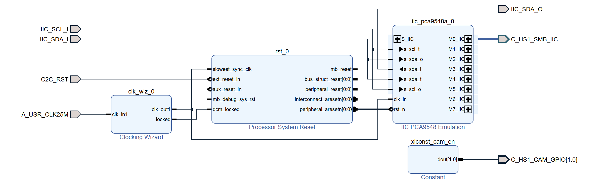
The Artix canvas is small. The 25 MHz clock comes in on the left, the I2C mux is on the right, and a constant holds the camera enable high.
- Add a Clocking Wizard:
- Input:
A_USR_CLK25M(25 MHz) - Output: 100 MHz, with
LOCKED
- Input:
- Add Processor System Reset:
slowest_sync_clk← 100 MHzdcm_locked←lockedext_reset_in←C2C_RST(the Versal drives this later)
- Add
iic_pca9548a:clk_in← 100 MHzrst_n←peripheral_aresetn
- Make ports
IIC_SCL_I,IIC_SDA_I, andIIC_SDA_O, and wire them to the mux the same way as the Trenz Artix reference. - Make
M0_IICexternal asC_HS1_SMB_IIC(the HS1 camera). - Add an xlconstant, width 2, value
3, and make it external asC_HS1_CAM_GPIOso the camera stays enabled.
Validate, create the wrapper, add hw_artix/constraints/te0950_artix_mipi.xdc, generate the bitstream, and program the Artix.
On the Versal UART I look for Artix: I2C mux @0x70 ACK. If that line never shows up, the Artix or C2C_RST is the problem, not the camera.
Step 2: Versal project
- Open Vivado 2024.2 → Create Project.
- Name e.g.
te0950_dual_mipi_udpand keep the path short. Long Windows paths cause trouble on Versal builds. - Boards tab → te0950_23_1lse.
- Finish.
- Create Block Design → name
system.
Step 3: CIPS clocks
Add Control, Interfaces and Processing System (versal_cips) and set:
| Clock / peripheral | Setting |
|---|---|
pl0_ref_clk | 100 MHz (video) |
pl1_ref_clk | 200 MHz (MIPI PHY) |
M_AXI_FPD | 128-bit |
| UART1 | PS MIO 12–13 |
| I2C0 | EMIO (over to the Artix) |
| GEM0 | PS MIO 0–11, MDIO on MIO 24–25 |
| IRQ | pl_ps_irq0 |
Run board automation so the DDR comes up with the TE0950 memory preset. The second SmartConnect, the one the frame writers use, goes in after those IPs exist.
Step 4: Resets and the register bus
- Add
proc_sys_resetrst_pl0onpl0_ref_clk, reset frompl0_resetn. - Add
proc_sys_resetrst_pl1onpl1_ref_clk, reset frompl0_resetn. - Add SmartConnect
axi_smc: 1 slave, 10 masters, clocked frompl0_ref_clk, reset fromrst_pl0. ConnectS00_AXItoversal_cips_0/M_AXI_FPD.
| Master | Goes to |
|---|---|
| M00 | mipi_csi_cam0 |
| M01 | mipi_csi_cam1 |
| M02 | axi_iic_cam0 |
| M03 | axi_gpio_cam0 |
| M04 | v_demosaic_cam0 |
| M05 | v_demosaic_cam1 |
| M06 | v_frmbuf_wr_cam0 |
| M07 | v_frmbuf_wr_cam1 |
| M08 | v_proc_ss_cam0 |
| M09 | v_proc_ss_cam1 |
Step 5: One camera pipe, then a copy
I built this once for J15 (*_cam0) and copied it for HS1 (*_cam1). Each CSI block has its own PHY PLL. Support level 1 means the PHY lives inside the CSI IP. The bank has two of those PLLs, which is why two cameras fit.
5a. MIPI CSI-2 Rx
Add mipi_csi2_rx_subsystem:
| Option | Value |
|---|---|
| Lanes | 2 |
| Pixel format | RAW10 |
| Pixels per clock | 2 |
| Include video format bridge | Yes |
| Include IIC | No |
| CSI-2 v2.0 / active lanes | Yes |
| Line rate | 1500 Mbps |
| Support level | 1 |
Clocks: video and AXI-Lite from the 100 MHz clock, PHY from the 200 MHz clock. Resets from the matching proc_sys_reset. Make mipi_phy_if external (cam0 / cam1).
5b. Demosaic
Add v_demosaic: 2 samples per clock, 10-bit, max 1920×1080, interpolation, zipper removal on. Clock and reset from the 100 MHz domain.
5c. Cut 10-bit colour down to 8-bit
Demosaic comes out as 10-bit RGB, two pixels at a time. VPSS wants 8-bit. An AXIS subset converter keeps the top 8 bits of each colour:
- Input width 8 bytes, output width 6 bytes
- Remap:
tdata[59:52],tdata[49:42],tdata[39:32],tdata[29:22],tdata[19:12],tdata[9:2]
Same 100 MHz clock and reset.
5d. VPSS, scale only
Add Video Processing Subsystem (v_proc_ss):
| Option | Value |
|---|---|
| Topology | Scaler only |
| Algorithm | Bilinear |
| Samples per clock | 2 |
| Data width | 8 |
| Components | 3 |
| Max size | 1920 × 1080 |
| DMA / interlaced | Off |
The IP is sized for 1080p. The software tells it the real scale later: 1920×1080 in, 320×180 out. Clock both the video and the control port from 100 MHz. aresetn_io_axis is an output, so leave it alone.
5e. Frame buffer write
Add v_frmbuf_wr: 128-bit memory port, 2 samples per clock, max 320×180, 8-bit, RGB8 on, one plane. Same 100 MHz clock and reset.
5f. Wire the video
mipi_csi_camX / video_out
  → v_demosaic_camX
  → axis subset
  → v_proc_ss_camX
  → v_frmbuf_wr_camX
At 1080p this is about 91 million beats a second on a 100 MHz clock, so it fits once VPSS is already running. If the CSI core is enabled while VPSS is still in reset, the picture stays black even though the packet counter keeps climbing. Start order is in the Vitis section.
Step 6: Both writers into DDR
- Add another SmartConnect,
axi_smc_mm: 2 slaves, 1 master, 100 MHz. - Frame writer cam0 →
S00, cam1 →S01. - Master into a PL port on the AXI NoC, on the 100 MHz clock.
- Leave the processor’s own NoC ports where board automation put them.
- Run Board Automation on the DDR pins if they are not already tied to
ddr4_bank0.
Only those two writers use DDR from the PL. The stitched frame sits in processor memory.
Step 7: J15 I2C, GPIO, and the Artix link
- AXI IIC
axi_iic_cam0at 100 kHz. MakeIICexternal ascam0_iic. - AXI GPIO
axi_gpio_cam0: width 2, all outputs, default0x3. MakeGPIOexternal ascam0_gpio. - Both on the 100 MHz clock and reset, on SmartConnect M02 and M03.
- Add
iic_to_3wire(mode 0) and connectversal_cipsI2C0 to it. - Ports
A_IIC_SCL_O,A_IIC_SDA_O,A_IIC_SDA_Iare the three wires to the Artix. C2C_RSTcomes fromrst_pl0. If the Artix is held in reset, the I2C mux never ACKs.
Step 8: Interrupts
xlconcat, 4 inputs:
| Input | From |
|---|---|
| In0 | cam0 CSI irq |
| In1 | cam1 CSI irq |
| In2 | cam0 frame writer |
| In3 | cam1 frame writer |
dout → versal_cips pl_ps_irq0.
The app just polls the frame writers. The interrupts are still wired so the platform looks normal.
Step 9: Constraints, addresses, bitstream
- Add
hw_versal/constraints/dual_mipi.xdc. - Address Editor → Assign All.
- Validate Design.
- Create the HDL wrapper and set it as top.
- Generate the bitstream and export the XSA with the bitstream included (
hw_versal/export/te0950_dual_mipi_udp.xsa).
Step 10: Vitis application
Standalone on psv_cortexa72_0. I turned on lwIP 2.2 with DHCP. lwIP is just the UDP/IP code linked into the bare-metal app. I also raised its packet-buffer count (MEMP_NUM_PBUF 256) so a frame of UDP headers does not run out halfway through. Sources are in sw_vitis/dual_mipi_udp/src/.
Per camera, in this order:
- Program the IMX219, leave streaming off.
- Start demosaic at 1920×1080.
- Start VPSS: 8-bit RGB, 2 pixels per clock, 1920×1080 in, 320×180 out, bilinear.
- Start the frame writer at 320×180, stride 960, RGB8.
- Then enable the CSI core.
The A72 waits until both writers have a frame, copies the tiles into a 640×180 buffer (cam1 starts at x = 320), and sends that. That copy is the stitch. More on why it is not done in the PL under Camera sync .
UDP goes to 192.168.8.220 port 55000, not a broadcast. Each packet is a 24-byte header (MIP1) plus up to 1460 bytes of pixels. A frame is 345600 bytes, 237 packets. I spread those packets across 40 ms so the PC can keep up. Sending them back to back fills the 100 Mbit link for about 29 ms and the PC was dropping about one packet in ten, which is where the black lines came from.
Step 11: How fast it actually runs
The 100 MHz clock, two pixels at a time, can take more than the cameras produce. The limit is the IMX219.
| Pixel clock | 182.4 MHz (the usual 2-lane setup, 912 Mbit/s per lane) |
| Line length | 3448 clocks, which is as short as this sensor allows |
| Frame length | 1113 lines |
182.4e6 / (3448 × 1113) is about 47.5 fps. The UART packet counters agree: roughly 52 000 lines a second is 1080 lines times about 48 fps. The scaler is not slowing it down.
The UDP output does not follow that. A 640×180 frame at 48 fps is about 141 Mbit/s, which is fine on gigabit and too much for the 100 Mbit fallback this PHY ends up on. 25 fps is the fastest I could receive here without missing packets.
720p at 60 fps, same output size
Same bitstream. Demosaic and VPSS already allow up to 1080p, and the frame writer max is 320×180, so a smaller camera picture still scales into the same tile.
Keep the same pixel clock and the 3448-clock line. A centred 1280×720 window and a frame length of 882 lines is 60 fps. Start the window on even pixels so the colour filter does not shift. Exposure has to be shorter than the frame (the 1080p exposure of 1088 lines is too long and the frame stretches back out).
| 720p | |
|---|---|
| X start / end | 1000 / 2279 |
| Y start / end | 872 / 1591 |
| Frame length | 882 |
Then tell demosaic and VPSS the input is 1280×720, and leave the VPSS output at 320×180. UDP is still the same 640×180 stitch at 25 fps.
Step 12: On the board
- Program the Artix bitstream.
- Program the Versal PDI and
dual_mipi_udp.elftogether. - UART on J2, 115200.
What I expect:
BUILD vpss-...  stitch 640x180 (320x180|320x180)
early PHY AN failed - force 100 FDX
Board IP 192.168.8.x
UDP -> 192.168.8.220:55000  paced <=25 fps
rate 25 fps  ... send=40ms skip=0  live=1/1
send=40ms is the gap I put between frames, not a stall. skip=0 means a new stitch was ready every time. The CSI packet counts still climb faster than 25 fps, because the cameras are free-running above the UDP rate.
A few things that cost me time:
- Start VPSS and both frame writers before enabling CSI. The other way around, the picture stays black while the packet count still goes up.
- lwIP does not change the Ethernet clock when the link drops to 100 Mbit. I set
CRL_GEM0_REF_CTRLDIV0 to 35. - 30 fps of this frame fits on a 100 Mbit wire if you count the bytes, and still falls apart if the packets go out in one burst. Spacing them out is what made complete frames.
- Load this PDI and this ELF together. A leftover PDI with this app looks almost right and then wastes an afternoon.
Step 13: The viewer
On the Windows PC on 192.168.8.0/24 (not WSL2):
python host\udp_viewer.py --rgb
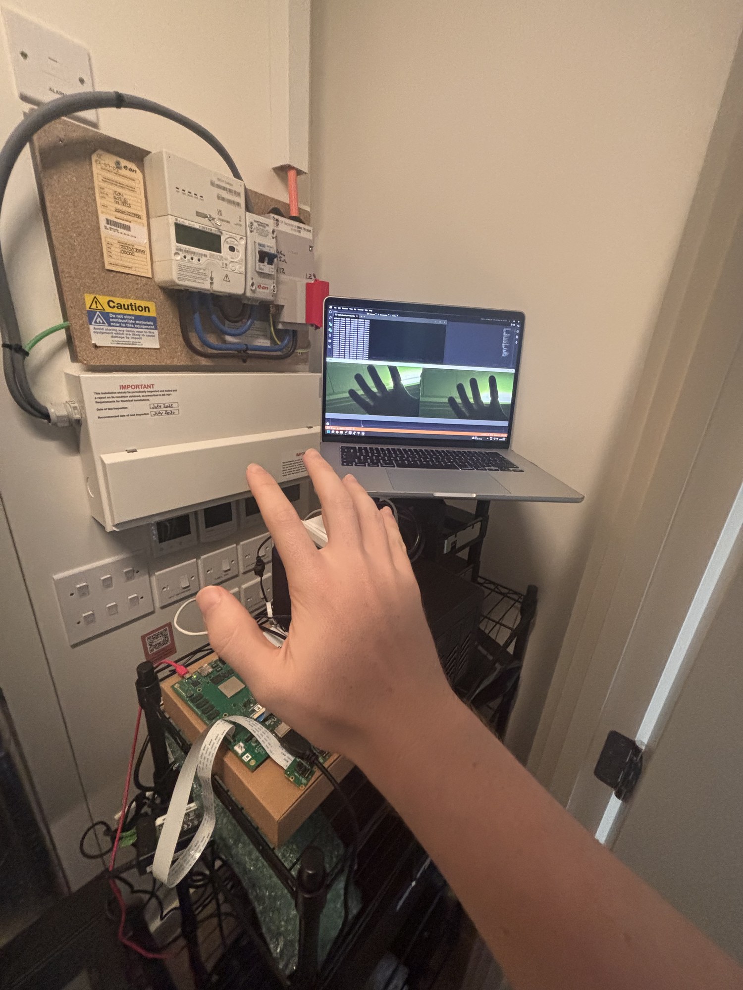
The board sends to 192.168.8.220. The viewer listens on UDP 55000 and only draws a frame when all 237 packets for that frame have arrived. Left half of the window is J15, right half is HS1.
Camera sync
The stitch is on the A72 because I could not lock the two sensors.
The IMX219 does have sync pins on the chip. The 15-pin flex on J15 and on the CR00240 does not bring them out. The pins that are there are camera enable and an LED. Both sensors free-run. Giving them the same line length and starting them together keeps them close, but they still drift, so a mixer in the PL never had two pictures that lined up.
The software just:
- Programs both cameras the same way.
- Starts them one after the other.
- Waits until both frame writers have a new tile, then copies that pair.
If something in the scene is moving fast, you can still see a few lines of offset between the two halves.
The next camera I want to try is an ArduCam OV5647 board. That one brings out FREX, which starts a frame when you pulse it. One pulse from the PL into both cameras would start them together. A normal Pi camera flex does not have that pin.
Project files
te0950_dual_mipi_udp.zip
is the Vivado scripts, constraints, the iic_to_3wire IP, the Vitis sources, and the viewer. fetch_trenz_refs.ps1 downloads the Trenz board files. The zip does not include the Vivado or Vitis build folders.
.\scripts\fetch_trenz_refs.ps1
.\scripts\build_artix.ps1
.\scripts\build_hw.ps1
.\scripts\build_sw_short.ps1
build_sw_short.ps1 builds on C:\t\vm2 because the Vitis path gets too long.
Acknowledgements
Thanks to Sundance for lending me the TE0950 board for this bring-up.
Updated on 2026-09-28