FPGA: Creating a MIPI PL pipeline on the TE0950
Overview
This project is on the 2024.2 Xilinx toolchain (Vivado + PetaLinux). The board is a TE0950-03 (xcve2302-sfva784-1LP-e-S, board part trenz.biz:te0950_23_1lse:part0:1.2). The camera sits on connector J15; UART is FTDI on J2 at 115200 8N1 (not the Vivado JTAG UART window).
The data path looks like this:
IMX219 (J15) → MIPI CSI-2 RX (2-lane RAW10)
  → AXIS subset → v_demosaic → VPSS CSC (UYVY)
  → v_frmbuf_wr → AXI NoC → DDR → V4L2 (/dev/video0)
  → GStreamer jpegenc → rtpjpegpay → UDP → VLC (SDP)
One important note up front: install the Trenz board files for the TE0950 first (Tools → Settings → Board Repository) so te0950_23_1lse shows up under the Boards tab.
Block Design
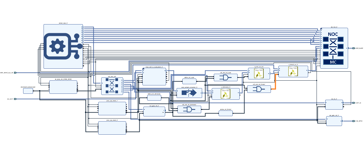
Block Design Breakdown
- Versal CIPS (
versal_cips): PS, PL clocks/resets, andM_AXI_FPDfor register access. Board preset + full system with DDR via NoC. - AXI NoC: PL frame-buffer master into DDR (plus the CIPS DDR ports).
- MIPI CSI-2 Rx Subsystem: 2-lane RAW10 from the IMX219 on J15.
- AXIS Subset Converter: Adapts CSI AXIS width / packing into the demosaic input.
- Sensor Demosaic (
v_demosaic): Bayer → RGB (max size at least 1080p; prefer headroom for the sensor’s full mode). - Video Processing Subsystem: Topology CSC only, 8-bit, producing UYVY for the frame buffer.
- Video Frame Buffer Write (
v_frmbuf_wr): Writes UYVY/YUYV into DDR over the NoC. - AXI IIC + AXI GPIO (
CSI_GPIO): Camera I2C and power / sideband pins brought external. - AXI GPIO (
axi_gpio_rst) + xlslice / util_vector_logic: Soft resets ANDed withproc_sys_reset— required by the Linux drivers. - proc_sys_reset (×2+): Separate domains for the 100 MHz video/AXI path and the 200 MHz D-PHY clock.
- AXI SmartConnect: Routes
M_AXI_FPDto CSI, demosaic, VPSS, frmbuf, GPIOs, and IIC.
Block Design Notes
The IPs themselves are fairly standard; the traps were the PL→PS IRQs and the soft-reset GPIO bank. Without IRQs on IIC / CSI / frmbuf you get IRQ index 0 not found and no PL I2C. Without reset-gpios in the device tree (and the AND with system reset in hardware), the demosaic / VPSS / frmbuf drivers refuse to probe cleanly.
Step 1: Create the Vivado project
- Open Vivado 2024.2 → Create Project.
- Name e.g.
mipi_exampleand keep the path short. - RTL Project → do not add sources yet.
- Boards tab → select te0950_23_1lse (Versal VE2302).
- Finish.
Step 2: Build the block design
Create Block Design → name mipi_example_bd.
Add Control, Interfaces and Processing System (versal_cips) and run Block Automation / the CIPS wizard with approximately:
- Board preset: Yes (Trenz)
- Design flow: Full System + DDR via NoC
- PL clocks:
pl0/ PL0: 100 MHz (video + AXI-Lite)pl1/ PL1: 200 MHz (MIPI D-PHY)
- PL resets: at least one (
pl0_resetn) - Enable M_AXI_FPD
- Give the NoC a PL slave for the frame buffer (e.g.
S08_AXI→ DDR MC) in addition to the CIPS DDR ports
Add and configure the video IPs
| IP | Key settings |
|---|---|
| MIPI CSI-2 Rx Subsystem | 2 lanes, RAW10, D-PHY present, video + lite AXI |
| AXIS Subset Converter | Adapt CSI AXIS width/TDATA to demosaic input |
Sensor Demosaic (v_demosaic) | Max ≥ 1920×1080 (prefer 3840×2464) |
| Video Processing Subsystem | Topology CSC only, 8-bit, samples/clk matching the pipeline (often 2) |
| Video Frame Buffer Write | UYVY/YUYV enabled, max size ≥ 1080p, AXI-MM to NoC |
| AXI IIC | External I2C → rename port cam1_iic |
AXI GPIO (axi_gpio_csi) | Width 2, all outputs → external CSI_GPIO |
AXI GPIO (axi_gpio_rst) | Width 3, all outputs, not external — Linux soft resets |
| proc_sys_reset ×2 (+ D-PHY domain) | Clocked from pl0 / pl1 as appropriate |
Connect the stream
mipi_csi2_rx / video_out
  → axis_subset_converter
  → v_demosaic / s_axis_video
  → v_proc_ss (CSC) / s_axis
  → v_frmbuf_wr / s_axis_video
  → v_frmbuf_wr / m_axi_mm_video → axi_noc PL DDR port
Make MIPI clk_p/n and data_p/n[1:0] external (map in XDC). Drive D-PHY 200 MHz from CIPS pl1_ref_clk (preferred; not a package pin).
Clocks, resets, and soft resets
- 100 MHz (
pl0): CSI video/lite, demosaic, VPSS, frmbuf, AXI IIC/GPIO, SmartConnect, NoC PL clock as required. - 200 MHz (
pl1): MIPIdphy_clk_200M+ D-PHYproc_sys_reset. - Wire
peripheral_aresetnfromproc_sys_resetinto IP*_aresetn/ap_rst_n.
For demosaic, VPSS, and frmbuf (required by Linux):
ap_rst_n / aresetn = (proc_sys_reset peripheral_aresetn) AND (axi_gpio_rst bit)
Use xlslice (bits 0/1/2) + util_vector_logic (AND). Default GPIO outputs high so the IPs are out of reset before probe (C_DOUT_DEFAULT ≈ 0x7).
Interrupts (required)
In CIPS → Interrupts → enable PL to PS channels CH0, CH1, CH2 so pl_ps_irq0/1/2 are exported.
| Source | Destination |
|---|---|
axi_iic iic2intc_irpt | pl_ps_irq0 |
MIPI csirxss_csi_irq | pl_ps_irq1 |
v_frmbuf_wr interrupt | pl_ps_irq2 |
AXI control path
Connect CSI, demosaic, VPSS, frmbuf, both GPIOs, and IIC S_AXI to CIPS M_AXI_FPD via SmartConnect (100 MHz). In the Address Editor, assign addresses (typical 0xA400_0000 region for PL).
Validate Design, Create HDL Wrapper (let Vivado manage it), and set the wrapper as top.
Step 3: Constraints (J15)
Add an XDC — update port names if your wrapper uses *_tri_io instead of *_tri_o:
# CSI GPIO
set_property PACKAGE_PIN F11 [get_ports {CSI_GPIO_tri_o[0]}]
set_property PACKAGE_PIN E11 [get_ports {CSI_GPIO_tri_o[1]}]
set_property IOSTANDARD LVCMOS33 [get_ports {CSI_GPIO_tri_o[*]}]

# Camera I2C
set_property PACKAGE_PIN A13 [get_ports cam1_iic_scl_io]
set_property PACKAGE_PIN B13 [get_ports cam1_iic_sda_io]
set_property IOSTANDARD LVCMOS33 [get_ports {cam1_iic_scl_io cam1_iic_sda_io}]

# MIPI D-PHY (TE0950_23_1lse)
set_property PACKAGE_PIN H25 [get_ports csi_cam1_clk_p]
set_property PACKAGE_PIN J26 [get_ports csi_cam1_clk_n]
set_property PACKAGE_PIN G25 [get_ports {csi_cam1_data_p[0]}]
set_property PACKAGE_PIN G26 [get_ports {csi_cam1_data_n[0]}]
set_property PACKAGE_PIN F26 [get_ports {csi_cam1_data_p[1]}]
set_property PACKAGE_PIN E26 [get_ports {csi_cam1_data_n[1]}]
set_property IOSTANDARD MIPI_DPHY [get_ports {csi_cam1_clk_p csi_cam1_clk_n}]
set_property IOSTANDARD MIPI_DPHY [get_ports {csi_cam1_data_p[*] csi_cam1_data_n[*]}]
Step 4: Implement and export the XSA
- Run Synthesis → Implementation → Generate Device Image (Versal PDI).
- File → Export → Export Hardware:
- Include bitstream / device image
- Fixed
- Output e.g.
mipi_example.xsa
Keep this XSA for PetaLinux.
Step 5: Configure PetaLinux
Source the 2024.2 settings script, then create a Versal project and import the XSA:
source /path/to/Petalinux_2024/settings.sh
cd ~/petalinux_projects
petalinux-create -t project -n mipi-example --template versal
cd mipi-example
petalinux-config --get-hw-description=/path/to/mipi_example.xsa
In menuconfig:
- Prefer EXT4 root on SD (not initramfs-only), with bootargs like
root=/dev/mmcblk1p2 ro rootwait(TE0950 SD is typicallymmcblk1) - Console:
ttyAMA0, 115200 (pl011 / earlycon on this board)
Kernel fragment
Under project-spec/meta-user/recipes-kernel/linux/, add a linux-xlnx_%.bbappend and files/kernel-fragment.cfg:
CONFIG_MEDIA_SUPPORT=y
CONFIG_MEDIA_CAMERA_SUPPORT=y
CONFIG_V4L_PLATFORM_DRIVERS=y
CONFIG_VIDEO_XILINX=y
CONFIG_VIDEO_XILINX_CSI2RXSS=y
CONFIG_VIDEO_IMX219=y
CONFIG_I2C=y
CONFIG_I2C_CHARDEV=y
Also enable CONFIG_I2C_XILINX and the frmbuf / demosaic / VPSS options in the Xilinx video stack (petalinux-config -c kernel if you need to hunt for names).
Rootfs
petalinux-config -c rootfs — enable (or add via user config):
packagegroup-xilinx-gstreamerv4l-utilsyavtai2c-toolslibgpiod-tools(optional)
Avoid enabling both Dropbear and OpenSSH if they conflict in 2024.2. The two apps below pull in the GStreamer / V4L2 dependencies they need via RDEPENDS.
Device tree (system-user.dtsi)
Path: project-spec/meta-user/recipes-bsp/device-tree/files/system-user.dtsi
Include Trenz board basics (SD, QSPI, ETH PHY on gem0, EEPROM MAC on i2c2) plus camera enablement:
- Status okay on MIPI CSI, demosaic, VPSS CSC, frmbuf,
axi_iic, and both GPIOs. - reset-gpios (active low) on demosaic / VPSS / frmbuf →
&axi_gpio_rst_0bits 0/1/2. - Fixed 24 MHz clock + regulators for the IMX219.
- IMX219 node on
axi_iic@0x10, linked to the CSI endpoint (data-lanes = <1 2>).
Example fragments (labels must match pl.dtsi):
&v_demosaic_0 {
	status = "okay";
	reset-gpios = <&axi_gpio_rst_0 0 GPIO_ACTIVE_LOW>;
};
&v_proc_ss_csc {
	status = "okay";
	compatible = "xlnx,v-vpss-csc";
	reset-gpios = <&axi_gpio_rst_0 1 GPIO_ACTIVE_LOW>;
};
&v_frmbuf_wr_0 {
	status = "okay";
	xlnx,dma-align = <32>;
	reset-gpios = <&axi_gpio_rst_0 2 GPIO_ACTIVE_LOW>;
};

&axi_iic_0 {
	status = "okay";
	#address-cells = <1>;
	#size-cells = <0>;
	imx219: camera-sensor@10 {
		compatible = "sony,imx219";
		reg = <0x10>;
		clocks = <&camera_clk>;
		clock-names = "xclk";
		VANA-supply = <&cam_reg1>;
		VDIG-supply = <&cam_dummy_reg>;
		VDDL-supply = <&cam_dummy_reg>;
		port {
			camera_out: endpoint {
				data-lanes = <1 2>;
				link-frequencies = /bits/ 64 <456000000>;
				remote-endpoint = <&mipi_csi_in>;
			};
		};
	};
};
After the build, confirm system.dtb has interrupts on the PL I2C / CSI / frmbuf nodes and reset-gpios on the video IPs.
PetaLinux apps
I added two apps under project-spec/meta-user/recipes-apps/:
mipi-pipeline-test— self-test (test-mipi-pipeline): I2C / media graph checks, configures the pipeline, captures UYVY frames withyavtamipi-example— bring-up helper (run-mipi-example.sh): snapshot, TCP JPEG, or UDP RTP/JPEG for VLC (writes an SDP)
mipi-pipeline-test
petalinux-create -t apps -n mipi-pipeline-test --enable
That creates:
project-spec/meta-user/recipes-apps/mipi-pipeline-test/
Copy the script and overlay into files/:
project-spec/meta-user/recipes-apps/mipi-pipeline-test/files/test-mipi-pipeline.sh
project-spec/meta-user/recipes-apps/mipi-pipeline-test/files/imx219-overlay.dtbo
chmod +x project-spec/meta-user/recipes-apps/mipi-pipeline-test/files/test-mipi-pipeline.sh
Replace the default recipe with:
Download mipi-pipeline-test.bb
On the target this installs test-mipi-pipeline to ${bindir} and the DTBO under /usr/lib/firmware/mipi-example/.
mipi-example
petalinux-create -t apps -n mipi-example --enable
That creates:
project-spec/meta-user/recipes-apps/mipi-example/
Copy into files/:
project-spec/meta-user/recipes-apps/mipi-example/files/run-mipi-example.sh
project-spec/meta-user/recipes-apps/mipi-example/files/mipi.sdp
chmod +x project-spec/meta-user/recipes-apps/mipi-example/files/run-mipi-example.sh
Replace the default recipe with:
That installs run-mipi-example.sh to ${bindir} and a template SDP under /usr/share/mipi-example/mipi.sdp.
Summary:
petalinux-create -t apps -n mipi-pipeline-test --enable(and the same formipi-example)- Copy the scripts / SDP / DTBO into each app’s
files/ - Replace each
.bbwith the recipes above - Rebuild so both packages land in the rootfs
Step 6: Build and flash the SD image
petalinux-build
Package BOOT.BIN with U-Boot + TF-A (Versal needs more than PDI-only):
petalinux-package boot --force \
  --u-boot images/linux/u-boot.elf \
  --tfa images/linux/bl31.elf \
  --dtb images/linux/system.dtb \
  --boot-script images/linux/boot.scr \
  -o images/linux/BOOT.BIN
Package the WIC (EXT4 root). Boot FAT should contain:
BOOT.BIN + Image + system.dtb + boot.scr
Do not leave a stale image.ub on the FAT if you use EXT4 root — U-Boot prefers FIT first if it is present.
petalinux-package wic \
  --bootfiles "BOOT.BIN Image system.dtb boot.scr" \
  --rootfs-file images/linux/rootfs.tar.gz \
  --size 512M,4G \
  -o images/linux
Flash the WIC to the SD card (dd or your usual imager), then seat the Cam v2 FFC on J15.
Step 7: Board bring-up
Power on with the SD card fitted, Cam v2 on J15, and UART on J2 @ 115200. Log in as petalinux (forced password change) and use sudo as needed.
Sanity checks:
ls /proc/device-tree/pl-bus/
# expect i2c@..., mipi_csi2..., v_demosaic, v_proc_ss, v_frmbuf_wr, gpio@...

dmesg | grep -iE 'xiic|imx219|mipi|frmbuf|demosaic|vpss'
i2cdetect -l
# expect xiic-i2c (often i2c-1) plus Cadence buses

ls -l /dev/media0 /dev/video0
Ethernet
The interface name is often end0 (not eth0).
Direct cable to the PC (no DHCP):
sudo ifconfig end0 192.168.0.10 netmask 255.255.255.0 up
On the PC set a static address in the same subnet (e.g. 192.168.0.20 / 255.255.255.0). Windows may show “Unidentified network” — that is fine for local streaming.
ping 192.168.0.20
Via DHCP:
sudo udhcpc -i end0
ifconfig end0
Step 8: Capture and stream to VLC
First run the self-test (configures the media graph and grabs frames):
sudo test-mipi-pipeline
Then stream RTP/JPEG to the PC with the example helper (SDP required for payload type 26):
UDP_HOST=192.168.0.20 UDP_PORT=5000 run-mipi-example.sh udp
Other modes: run-mipi-example.sh snapshot (yavta to /tmp) or run-mipi-example.sh video (TCP multipart JPEG on port 5001).
The UDP path writes /tmp/mipi.sdp. On the PC, open that SDP in VLC (Media → Open File) — do not rely on bare rtp://@:5000. Allow UDP 5000 through the firewall.
Example SDP:
v=0
o=- 0 0 IN IP4 192.168.0.20
s=TE0950 MIPI
c=IN IP4 192.168.0.20
t=0 0
m=video 5000 RTP/AVP 26
a=rtpmap:26 JPEG/90000
Acknowledgements
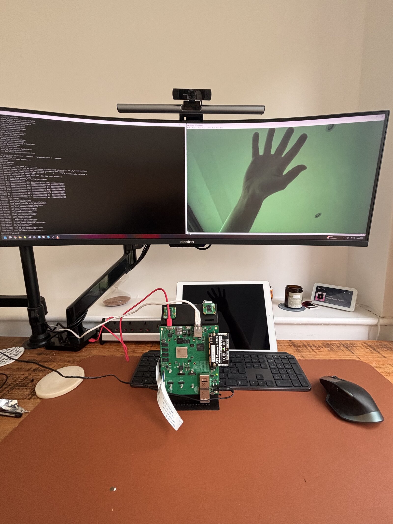
Thanks to Sundance for lending me the TE0950 board for this bring-up.