FPGA: Test Pattern Generator pipeline using Vivado 2025.2
Overview
I am currently running this project on the 2025.2 Xilinx toolchain. I’ve been looking at setting up a video pipeline in Vivado and PetaLinux. Due to the lack of camera connectivity I currently possess, I decided I would try and implement the test pattern generator IP. The idea is to, in the future, replace the TPG with a MIPI block to allow for camera connectivity. For this project I have created the block design and configured PetaLinux to allow me to create a pipeline to show the TPG output using OpenCV.
Block Design
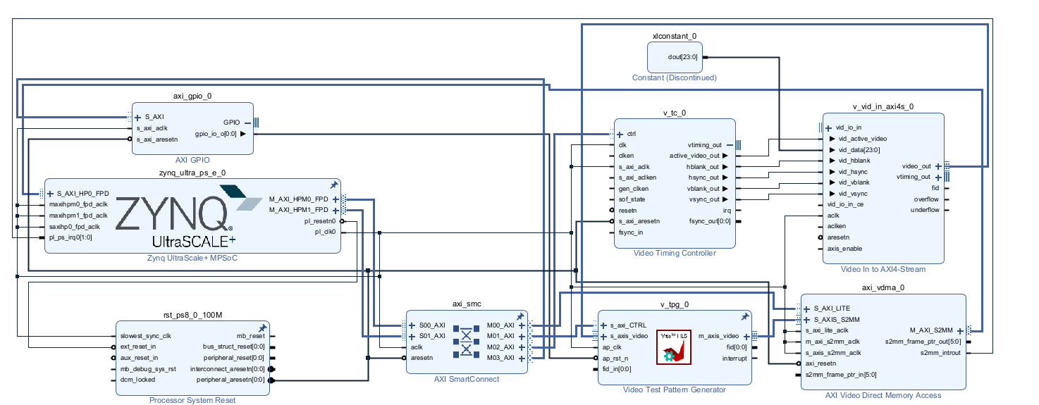
Block Design Breakdown
Zynq UltraScale+ MPSoC (bottom‑left): Provides the main clocks, resets and AXI control interfaces. It’s the system “brain” that configures the other blocks.
Video Timing Controller (VTC, mid‑left): Generates the video timing signals (hsync/vsync, active video, etc.) that define the resolution and frame timing for the pipeline.
AXI GPIO + constants/concat (top‑left / right): Used for simple control/status signals from the PS, plus fixed values and bit‑packing to drive enables/interrupts into the rest of the design.
AXI SmartConnect (bottom‑centre): AXI interconnect that routes the PS’s AXI master ports to the VDMA and TPG control interfaces.
AXI VDMA (centre‑right): Handles AXI4 memory reads/writes so video frames can be moved between DDR memory and the streaming video path.
Video Test Pattern Generator (TPG, bottom‑right): Generates a configurable AXI4‑Stream video pattern (colour bars, etc.), which is then fed through the VDMA / video path defined by the surrounding connections.
Block Design Notes
I found that the documentation for the TPG made it sound like it was a much more plug-and-play block than it really was. For example, there is an AXI GPIO block due to a requirement in the driver for one which I could not find any documentation on, which was frustrating. The VDMA, on the other hand, was reasonably easy to implement. P
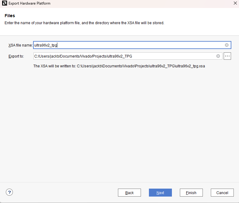
Exporting Hardware XSA
After running synthesis, implementation, and generating the bitstream, I created the hardware XSA, which I use to tell PetaLinux how to do the initial configuration. Make sure to include the bitstream!
Configuring PetaLinux
Before creating the PetaLinux project, make sure to copy your exported XSA file (named ultra96v2_tpg.xsa) into the base directory for easy access. For organization, I placed mine in a folder called troute at the root of my workspace.
Now, create your PetaLinux project targeting the ZynqMP platform (used by the Ultra96-V2):
petalinux-create -t project --template zynqMP --name ultra96v2_tpg_petalinux
Change into your new project directory:
cd ultra96v2_tpg_petalinux
To configure the hardware, pass your XSA file to the project. When running the command, point --get-hw-description to the parent directory (where the troute folder and your XSA live), like so:
petalinux-config --get-hw-description=../ultra96v2_tpg.xsa
Setting Serial and Filesystem
Next, configure the serial port settings to use UART1 and ensure that all relevant serial console options are set correctly for the Ultra96V2. In the PetaLinux configuration menu (petalinux-config), set the following:
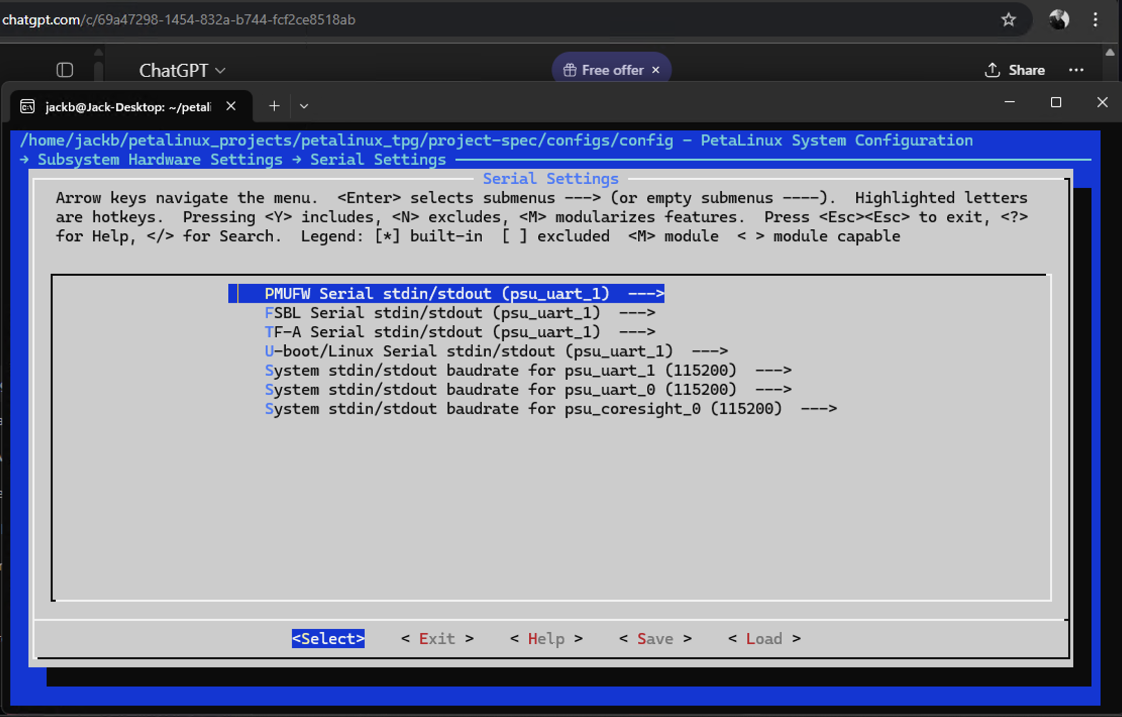
- Subsystem AUTO Hardware Settings → Serial Settings
Primary stdin:psu_uart_1Primary stdout:psu_uart_1Primary stderr:psu_uart_1Serial port:psu_uart_1
This will route the Linux console and all system messages through UART1 (ttyPS1), which matches the onboard UART header typically exposed on Ultra96V2 boards.
For filesystem configuration, select ext4 as the root filesystem type. This provides robustness and journaling for development and deployment:
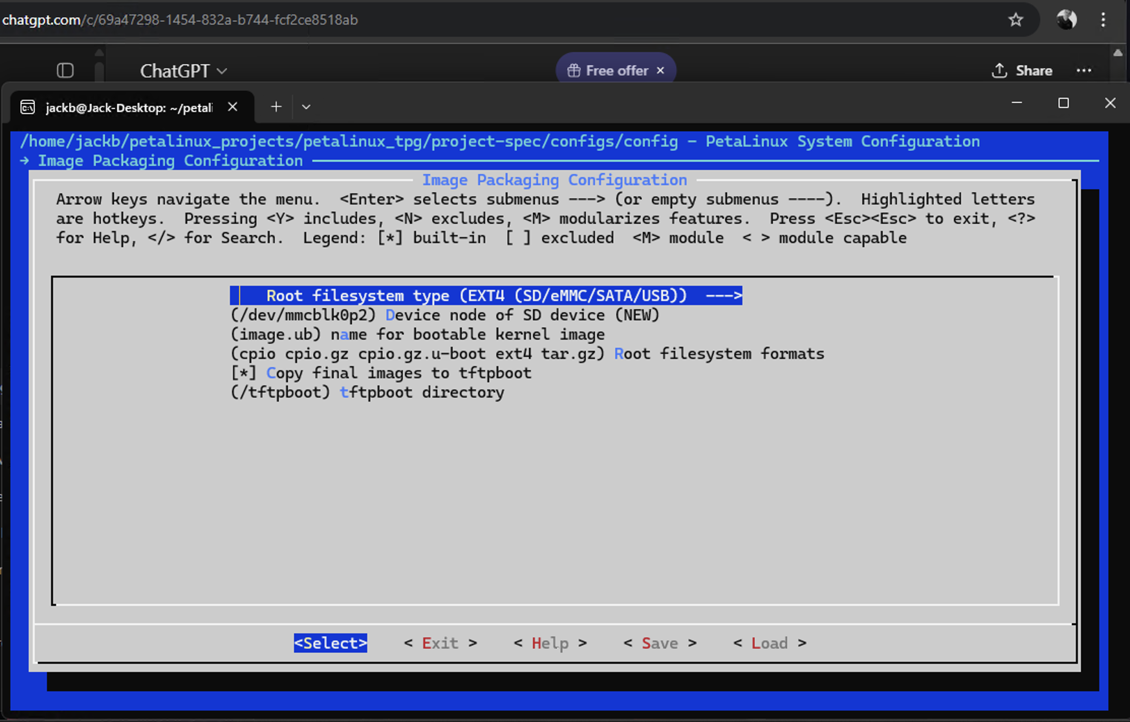
- Image Packaging Configuration → Root filesystem type
- Select:
ext4
- Select:
Device-tree: Set Machine Name
You will also want to set the machine name in the device tree settings to ensure full compatibility with the Ultra96-V2 board. In the PetaLinux configuration menu, navigate to the DTG Settings to update this value.
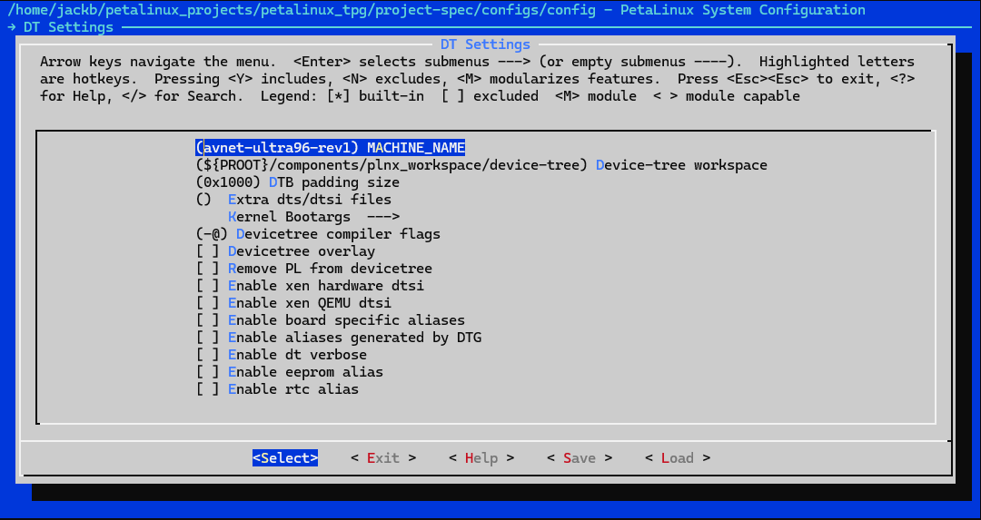
- DTG Settings → Machine Name
- Change this value to:
avnet-ultra96-rev1
- Change this value to:
Setting the machine name explicitly ensures proper board support and loads the correct board-specific configuration and overlays during boot.
Kernel Configuration via bsp.conf (project-spec/meta-user/recipes-kernel/files)
Next, configure the kernel features required for USB and networking by editing the bsp.conf file located in the recipes-kernel/files directory of your PetaLinux project.
Add or ensure the following configuration options are present in your bsp.conf:
CONFIG_USB_NET_DRIVERS=y

CONFIG_USB=y
CONFIG_USB_GADGET=y
CONFIG_USB_GADGET_VBUS_DRAW=2
CONFIG_USB_GADGET_STORAGE_NUM_BUFFERS=2
CONFIG_USB_GADGET_XILINX=y
CONFIG_USB_LIBCOMPOSITE=y
CONFIG_USB_F_ACM=y
CONFIG_USB_F_SS_LB=y
CONFIG_USB_U_SERIAL=y
CONFIG_USB_U_ETHER=y
CONFIG_USB_F_SERIAL=y
CONFIG_USB_F_OBEX=y
CONFIG_USB_F_NCM=y
CONFIG_USB_F_ECM=y
CONFIG_USB_F_EEM=y
CONFIG_USB_F_SUBSET=y
CONFIG_USB_F_RNDIS=y
CONFIG_USB_F_MASS_STORAGE=y
CONFIG_USB_F_FS=y
CONFIG_USB_F_UAC1=y
CONFIG_USB_F_UAC2=y
CONFIG_USB_F_UVC=y
CONFIG_USB_F_MIDI=y
CONFIG_USB_F_HID=y
CONFIG_USB_F_PRINTER=y
CONFIG_USB_CONFIGFS=y
CONFIG_USB_CONFIGFS_SERIAL=y
CONFIG_USB_CONFIGFS_ACM=y
CONFIG_USB_CONFIGFS_OBEX=y
CONFIG_USB_CONFIGFS_NCM=y
CONFIG_USB_CONFIGFS_ECM=y
CONFIG_USB_CONFIGFS_ECM_SUBSET=y
CONFIG_USB_CONFIGFS_RNDIS=y
CONFIG_USB_CONFIGFS_EEM=y
CONFIG_USB_CONFIGFS_MASS_STORAGE=y
CONFIG_USB_CONFIGFS_F_LB_SS=y
CONFIG_USB_CONFIGFS_F_FS=y
CONFIG_USB_CONFIGFS_F_UAC1=y
CONFIG_USB_CONFIGFS_F_UAC1_LEGACY=y
CONFIG_USB_CONFIGFS_F_UAC2=y
CONFIG_USB_CONFIGFS_F_MIDI=y
CONFIG_USB_CONFIGFS_F_HID=y
CONFIG_USB_CONFIGFS_F_UVC=y
CONFIG_USB_CONFIGFS_F_PRINTER=y
CONFIG_USB_GADGETFS=y
CONFIG_USB_STORAGE=y
CONFIG_USB_UAS=y

#
# Enable SPI user mode driver
#
CONFIG_SPI_SPIDEV=y

#
# Networking configurations
#
CONFIG_NF_TPROXY_IPV4=m
CONFIG_NF_TPROXY_IPV6=m

CONFIG_MEDIA_SUBDRV_AUTOSELECT=y

CONFIG_MEDIA_TUNER_MC44S803=y
CONFIG_MEDIA_TUNER_MT20XX=y
CONFIG_MEDIA_TUNER_SIMPLE=y
CONFIG_MEDIA_TUNER_TDA18271=y
CONFIG_MEDIA_TUNER_TDA827X=y
CONFIG_MEDIA_TUNER_TDA8290=y
CONFIG_MEDIA_TUNER_TDA9887=y
CONFIG_MEDIA_TUNER_TEA5761=y
CONFIG_MEDIA_TUNER_TEA5767=y
CONFIG_MEDIA_TUNER_XC2028=y
CONFIG_MEDIA_TUNER_XC4000=y
CONFIG_MEDIA_TUNER_XC5000=y

CONFIG_CMA_SIZE_MBYTES=1024
This enables the necessary USB, SPI, networking, and media features required for most development and prototyping scenarios on the Ultra96-V2 board. After saving the modified bsp.conf, rebuild your PetaLinux project so these kernel options are included in your next build.
Device Tree Configuration
You can find system-user.dtsi in your PetaLinux project at project-spec/meta-user/recipes-bsp/device-tree/files/system-user.dtsi.
Update the file as follows to configure the Test Pattern Generator (TPG) for correct communication with the VDMA:
/include/ "system-conf.dtsi"

/ {
    vcap_v_tpg_0 {
        /* capture must use S2MM channel (index 1) */
        dmas = <&axi_vdma_0 1>;
        dma-names = "port0";
    };
};

/* Override existing port nodes from pl.dtsi */
&tpg_port0v_tpg_0 {
    xlnx,video-format = <2>;  /* YUV422 */
    xlnx,video-width  = <8>;  /* 8-bit as per TPG config */
};

&tpg_port1v_tpg_0 {
    xlnx,video-format = <2>;
    xlnx,video-width  = <8>;
};

&v_tpg_0 {
    xlnx,vtc = <&v_tc_0>;
};
Place this in project-spec/meta-user/recipes-bsp/device-tree/files/system-user.dtsi within your PetaLinux project directory.
After editing, rebuild your device tree and project for the changes to take effect. This will ensure the TPG and VDMA are properly configured and communicate as required.
Root Filesystem Configuration
To enable the recommended tools and utilities for development with the Test Pattern Generator pipeline, update your PetaLinux root filesystem configuration file project-spec/configs/rootfs_config by ensuring the following options are set (y). This will include extra diagnostic, media, graphical, network, and FPGA management utilities necessary for most development scenarios:
CONFIG_system-zynqmp=y

CONFIG_e2fsprogs-mke2fs=y

CONFIG_fpga-manager-script=y

CONFIG_mtd-utils=y

CONFIG_can-utils=y

CONFIG_nfs-utils=y

CONFIG_pciutils=y

CONFIG_run-postinsts=y

CONFIG_gtkPLUS=y

CONFIG_gtkPLUS-dev=y

CONFIG_libgail=y

CONFIG_gtkPLUS-dbg=y

CONFIG_gtkPLUS3=y

CONFIG_gtkPLUS3-dev=y

CONFIG_gtkPLUS3-dbg=y

CONFIG_libdfx=y

CONFIG_udev-extraconf=y

CONFIG_linux-xlnx-udev-rules=y

CONFIG_gstreamer1.0-plugins-good=y

CONFIG_gstreamer1.0-plugins-good-dev=y

CONFIG_gstreamer1.0-plugins-good-dbg=y

CONFIG_gstreamer1.0-plugins-good-meta=y

CONFIG_packagegroup-core-boot=y

CONFIG_packagegroup-core-x11=y

CONFIG_packagegroup-core-x11-dev=y

CONFIG_packagegroup-core-x11-dbg=y

CONFIG_tcf-agent=y

CONFIG_v4l-utils=y

CONFIG_media-ctl=y

CONFIG_gstreamer1.0=y

CONFIG_gstreamer1.0-dev=y

CONFIG_gstreamer1.0-dbg=y

CONFIG_bridge-utils=y

CONFIG_dosfstools=y

CONFIG_u-boot-tools=y

CONFIG_packagegroup-opencv=y

CONFIG_packagegroup-opencv-dev=y

CONFIG_packagegroup-opencv-dbg=y

CONFIG_imagefeature-ssh-server-openssh=y

CONFIG_imagefeature-hwcodecs=y

CONFIG_imagefeature-package-management=y

CONFIG_Init-manager-systemd=y

CONFIG_tpg-viewer=y

CONFIG_usb-gadget-ethernet=y
After updating and saving rootfs_config, rebuild your PetaLinux project to ensure these packages are included in your image.
This provides a full development environment with networking, FPGA support, OpenCV, GStreamer, media capture/control, essential X11 packages, and debugging tools for your Ultra96-V2 TPG pipeline.
Step: Create a PetaLinux App for usb-gadget-ethernet
To create and integrate a PetaLinux application for usb-gadget-ethernet, use the following process:
1. Create the Application Skeleton
In your PetaLinux project directory, create the app using the proper PetaLinux command:
petalinux-create -t apps -n usb-gadget-ethernet --enable
This will create the folder structure at:
project-spec/meta-user/recipes-apps/usb-gadget-ethernet/
2. Add the Application Script
Copy the script from:
Download usb_gadget_ethernet.sh
into the app files directory:
project-spec/meta-user/recipes-apps/usb-gadget-ethernet/files/usb_gadget_ethernet.sh
Make sure it is executable:
chmod +x project-spec/meta-user/recipes-apps/usb-gadget-ethernet/files/usb_gadget_ethernet.sh
3. Replace the Bitbake Recipe
Replace the default usb-gadget-ethernet.bb in
project-spec/meta-user/recipes-apps/usb-gadget-ethernet/
with the provided one from:
Download usb-gadget-ethernet.bb
4. Build and Deploy
After the previous steps, rebuild your PetaLinux project:
Your script will be installed on the target at /home/root/usb_gadget_ethernet.sh.
Summary of steps:
petalinux-create -t apps -n usb-gadget-ethernet --enable- Copy
usb_gadget_ethernet.shinto the app’sfiles/ - Replace the
.bbrecipe with the provided one
Adding the tpg-viewer App to PetaLinux
The following steps will allow you to integrate the tpg-viewer (a minimal OpenCV+GStreamer video test pattern viewer) into your PetaLinux root filesystem for easy deployment/testing.
1. Create the Application
From your project root, run:
petalinux-create -t apps -n tpg-viewer --enable
This creates the app structure at:
project-spec/meta-user/recipes-apps/tpg-viewer/
2. Add the Application Source File
Copy the C++ source from:
to your new app’s files directory:
project-spec/meta-user/recipes-apps/tpg-viewer/files/tpg-viewer.cpp
3. Replace the Bitbake Recipe
Replace the default tpg-viewer.bb in
project-spec/meta-user/recipes-apps/tpg-viewer/
with the provided Bitbake recipe at:
This ensures the OpenCV tpg_viewer utility is built with the correct dependencies and install paths.
The tpg_viewer binary will be built and installed to ${bindir} (typically /usr/bin) on your target.
Summary of steps:
petalinux-create -t apps -n tpg-viewer --enable- Copy
tpg-viewer.cppinto the app’sfiles/ - Replace the
.bbrecipe with the provided one
After deploying, you can run tpg_viewer on your target to display video from /dev/video0.
4. Build the Project and Create the Boot Image
Build the complete PetaLinux project:
petalinux-build
After the build finishes, create the bootable BIN file using:
petalinux-package --boot --format BIN \
  --fsbl ./images/linux/zynqmp_fsbl.elf \
  --u-boot \
  --pmufw ./images/linux/pmufw.elf \
  --fpga \
  --dtb ./images/linux/system.dtb \
  --force
This command packages together the FSBL, PMU firmware, FPGA bitstream, U-Boot, and device tree into a single bootable file (BOOT.BIN) for the ZynqMP platform.
5. Create Deployable Image with WIC
To generate a deployable disk image (such as a .wic for SD card or eMMC boot), package your build using:
petalinux-package wic
This will generate the full .wic image file, typically in images/linux/, suitable for direct writing to your SD card.
Summary of next steps:
petalinux-buildpetalinux-package --boot ...(as above)petalinux-package --wic
After these steps, you will have BOOT.BIN, image.ub, and a WIC disk image ready for deployment to your Ultra96-V2.
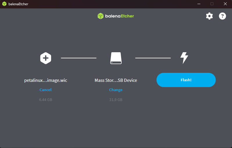
6. Write the WIC Image to SD Card
Now that you have the .wic image, you can write it to your SD card using balenaEtcher
or a similar tool:
- Insert the SD card into your PC.
- Open balenaEtcher.
- Select the generated
.wicimage file (e.g.,images/linux/plnx-aarch64.wic). - Choose your SD card as the target.
- Click “Flash” to program the SD card.
After Etcher completes, safely eject the SD card and insert it into your Ultra96-V2 board to boot your new image.
Configuring Host
Boot the Ultra96-V2 and Enable USB Ethernet
With the SD card prepared, insert it into the Ultra96-V2. Before powering on, connect a USB cable to the micro USB port at the front of the board—this port will act as a USB Ethernet interface once the board boots.
- Insert the flashed SD card into the board’s SD slot.
- Connect a micro USB cable from the front port of the Ultra96-V2 to your host PC or another device (this enables the USB Ethernet gadget).
- Power on the Ultra96-V2 by plugging in the barrel jack.
- The board will boot from the SD card. Once fully booted, your host PC should recognize a new Ethernet adapter via USB.
Depending on your system, the ethernet gadget may take a few moments to enumerate. You can then use SSH, SCP, or other network tools to interact with the board over the USB connection.
Once the board is powered and booted, you’ll want to access the Linux console to finalize network setup. On Windows, you can use PuTTY to connect via serial:
- Open PuTTY and select the Serial connection type.
- Set the Serial line to the appropriate COM port (often
COM6for the Ultra96-V2 when using a USB-to-serial cable).- Baud rate:
115200 - Data bits:
8 - Stop bits:
1 - Parity:
None - Flow control:
None
- Baud rate:
- Click Open.
Once connected and you see the login prompt, authenticate as root user:
sudo su root
4. Navigate to the /home/root directory:
cd /home/root
5. Run the USB Ethernet gadget script to manually activate the interface:
./usb_gadget_ethernet.sh
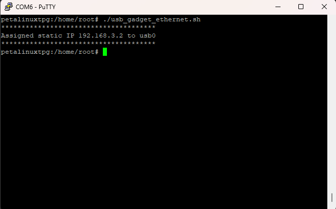
Your board’s USB Ethernet interface should now be operational and accessible from your host PC.
Configure Host Network
With the USB Ethernet gadget active, configure your host so it can talk to the Ultra96-V2 over the new USB network interface.
On Windows (Control Panel → Network and Internet → Network Connections):
- Identify the new USB Ethernet or RNDIS adapter that appeared when the board booted.
- Open its Properties → Internet Protocol Version 4 (TCP/IPv4).
- Set a static IP, for example:
- IP address:
192.168.137.1 - Subnet mask:
255.255.255.0 - Leave gateway/DNS blank or configure as needed.
- IP address:
On Linux (host PC):
- Identify the interface (often named
usb0,enx..., or similar):ip addr - Assign a static IP that matches the gadget subnet:Replace
sudo ip addr add 192.168.137.1/24 dev usb0 sudo ip link set usb0 upusb0with the actual interface name if different.
- Identify the interface (often named
The gadget script configures the Ultra96-V2 side at 192.168.137.2/24, so your host must be on the same /24 network (for example 192.168.137.1) to communicate.
Set Up Pipeline
Now that the USB Ethernet gadget is operational, you can disconnect from the serial console and connect to the Ultra96-V2 board using SSH from your development environment (for example, WSL on Windows).
To do this with X11 forwarding for GUI applications (like OpenCV video viewers), use the -X flag:
ssh -X root@192.168.137.2
The IP 192.168.137.2 assumes your board is using the static address set in the USB Ethernet gadget script. Adjust if you customized your gadget setup.
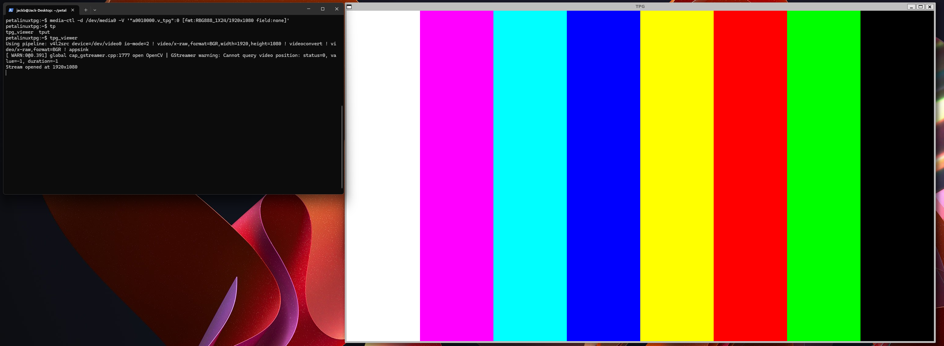
1. Set up the video pipeline using media-ctl to configure the TPG (Test Pattern Generator) video node format. Run:
media-ctl -d /dev/media0 -V '"a0010000.v_tpg":0 [fmt:RBG888_1X24/1920x1080 field:none]'
This command explicitly sets the TPG video format to 1920x1080 RGB. Replace "a0010000.v_tpg" with the exact entity name for your design if it differs (you can enumerate all nodes with media-ctl -p).
2. Launch your TPG video viewer application:
./tpg_viewer
If tpg_viewer was compiled as described previously and X11 forwarding is working, this should pop up a window on your host displaying the test image streamed from the TPG hardware block!